Coplanar MIM-Capacitor to Ground C_CAPLIN
Symbol :

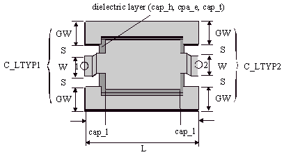
Illustration :

Parameters :
L = Total length of the capacitor
C_LTYPC = ID of coplanar transmission line applied at the capacitive section
C_LTYP1 = ID of coplanar transmission line applied at port 1
C_LTYP2 = ID of coplanar transmission line applied at port 2
DIE_IDX = Index to dielectric layer definition for capacitors in currently selected foundry (die_h, die_er, die_td)
C_SUB = ID of coplanar substrate definition
C_GRID = ID of simulation control data
TEMP = ID of element temperature definition used for noise computation
Notes/Equations/References :
- The C_CAPLIN module is introduced to have a capacitive connection between center conductor and ground planes (shunt capacitance to the ground).
- The width of capacitor and its distance to the ground are given in a line type addressed by C_LTYPC.
- The effective length of the capacitor is given by L-2*cap_l (see Layout). L must be greater than 2*cap_l.
- Presently, the C_CAPLIN module is not able to calculate the steps which are made if different line width W are used in C_LTYP1, C_LTYP1 and C_LTYPC. Therefore, if a step configuration is used for layout reasons, the effect of the step is not taken into account during the simulation.
- The lines addressed by C_LTYP1 and C_LTYP2 must have the same CEN_MET.
- CEN_MET in C_LTYPC must differ from CEN_MET in C_LTYP1 and C_LTYP2.
- The index DIE_IDX indicates the dielectric layer used for the capacitor. In case of DEFAULT foundry, two different dielectric layers are available (DIE_IDX =0 is not allowed). If DIE_IDX=1, the parameter die_h1, die_er1, die_td1, cap_l1 and cap_os1 are used.
- The oversize of lower metal plate is defined by the keyword cap_os in selected foundry. Note, that the parameter cap_l must be greater than 2*cap_os.
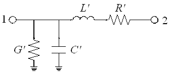
Equivalent Circuit :
For the modeling of the C_CAPLIN element, a distributive equivalent circuit is used and the model parameter are derived from 3D-FDM field calculations. As a result, there is no limitation regarding the length L of the capacitor. The metallization losses due to the skin effect as well as, the dielectric loss (represented by G´) of the dielectric material is taken into account.
Layout :
- Depending on the metal level of coplanar lines applied to the ports (C_LTYP1 and C_LTYP2) and the line used for the capacitive section (C_LTYPC), there are two ype of capacitors.


