[to index] [close window] [6 Coplanar Coupled Elements]

Coplanar Coupled Lines C_2COUP . . . C_10COUP

Symbol :

Illustration :

Parameters :

L = Length of coupled lines (stretchable)
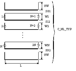
C_NL_TYP = ID of applied coplanar coupled lines at ports
C_SUB = ID of coplanar substrate definition
C_GRID = ID of simulation control data
TEMP = ID of element temperature definition used for noise computation

Notes/Equations/References :

  1. A zero or negative value for L can be meaningful during the simulation. In such cases, the automatic layout generation works incorrectly and the generated layout has to be edited manually. The minimum value for L depends on the metal layer oversize in the currently selected foundry. In case of DEFAULT foundry, L should be greater than or equal to max(|cond_os|, |cond2_os|).

  2. C_NL_TYP is the ID of the data item in which the geometrical dimensions of the coupled lines are defined. See descriptions in C_NL_TYP for more information.

  3. If L1 in selected C_GRID is not set to –1 or –2 (auto sizing), the minimum value for L1 depends on the nmber of coupled lines and has to be:

    L1min=W1+W2+ ...+2*(S1_2 + S2_3 + ...)+SG1+SG2+2*GW


Equivalent Circuit :

See Figure 6-1 and related descriptions at the beginning of this chapter.

Layout :

  1. Center lines and ground planes can have different metal level identification.

  2. The layout of coupled lines is stretchable. Use menu point (Edit - Trace/Transmission Line Stretch Transmission Line) in layout window in order to stretch the lines.

[to index] [close window] [7 IMST-Utilities]