[to index] [close window]

Coplanar Waveguide RF-Port C_PORT

Symbol :

Illustration :

Parameters :

C_PORT = port number
L = Length of port-section (not used in DEFAULT foundry)
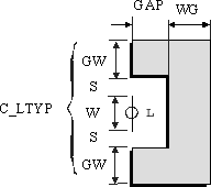
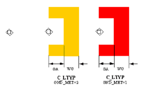
GAP = Gap (spacing) between the end of the center conductor and ground plane (only for TYPE = Ground_Connection )
WG = Width of ground plane at the end of the center conductor
(only for TYPE = Ground_Connection)
TYPE = Type of RF-port (see Notes)
C_LTYP = ID of Coplanar Transmission Line applied at port 1

Range of Usage :

TYPE = Ground_Connection, No_Ground_Connection

Notes/Equations/References :

  1. The C_PORT module is introduced only for layout generation (an schematic representation is also available). Therefore this module has no effect on simulation results. The post dimensions are defined using the coplanar line addressed by C_LTYP (see C_LINTYP).

  2. The parameter L is ignored in case of DEFAULT foundry.

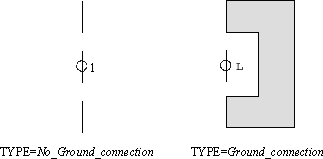
  3. The illustration
    shows the
    port types available.


  4. If TYPE=No_Ground_Connection is selected, the parameter WG and GAP are ignored.

  5. See notations in chapter 4 (Important Note!) for the correct selection of the C_LTYP.
Layout :

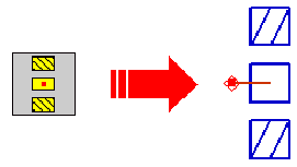
  1. If TYPE=No_Ground_Connection is selected, only a port symbol is drawn as layout, for TYPE=Ground_Connection only the ground planes will appear as layout.
  2. If the parameter GW_DEF in C_PROCES is set to a positive non-zero value, this value is used as ground width for layout generation


[to index] [close window]