Coplanar Substrate Data Definition C_SUB
Symbol :

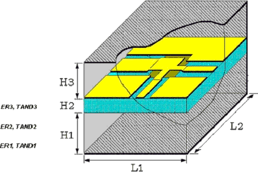
Illustration :

Parameters :
H1 = Height of substrate layer 1 (H1= -1, –2 ® auto sizing)
H2 = Height of substrate layer 2
H3 = Height of substrate layer 3 (H3= -1, –2 ® auto sizing )
ER1 = Relative permittivity of layer 1
ER2 = Relative permittivity of layer 2
ER3 = Relative permittivity of layer 3
TAND1 = Dielectric loss factor of substrate layer 1 (not used in this version!)
TAND2 = Dielectric loss factor of substrate layer 2
TAND3 = Dielectric loss factor of substrate layer 3 (not used in this version!)
Range of Usage :
H1 = 4.n.DL* n=0,1,2,...
H2 = n.DL* n=4,5,6,...
H3 = (4.n+ 3).DL* n=2,3,...
ER1 ³ 1
ER2 ³ 1
ER3 ³ 1
* ) see C_GRID for information on DL
Notes/Equations/References :
- C_SUB contains the parameters for a three layered substrate. For each layer, the substrate height and dielectric constant as well as the loss tangent can be specified.
- As it is given above (Range of Usage), the parameter H1, H2 and H3 must be an integer multiple of DL (see C_GRID for more information on DL), so that the top and bottom electric walls as well as the dielectric layer boundaries lie on the grid. However, if the user specify a maximum deviation from grid (ACC in selected C_GRID), the simulator can adapt the incompatible dimensions into the grid by changing these dimensions slightly (warnings will be reported). For ACC=0 (no deviation from grid) the simulator reports error and the next compatible value for the parameter will be suggested in the error message.
- In case of coplanar lines and in order to keep the effects of upper and lower cover as small as possible, H1 and H3 should be as large as possible. The simulator adapts automatically the values for H1 and H3 on the structure, if these parameters are set to –1 or –2 (auto sizing). A value of –1 for H1 and H3 is recommended.
- If the user like to investigate the effects of upper or lower cover on structure characteristics, H1 and H3 can be specified manually. For such applications, the minimum values for H1 and H3 and their compatibility to the grid (Range of Usage) have to be considered.
- Set H1=0 for the simulation of so called conductor-backed coplanar line (or to simulate the situation, when the substrate leis on metal during the on wafer measurements). The parameter H3 can be used or the simulation of packaging effects.
- ER1 and ER2 can have any arbitrary value greater than or equal to 1. Set ER1 and ER3 to 1 (air) for the simulation of simple coplanar lines.

