[close window] [Traweling Wave Amplifier]

Coplanar Interdigital Coupler


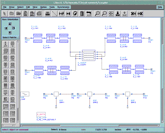
The example number four is an interdigital coupler using 4 coupled coplanar lines. The schematic of the circuit is shown in Figure 9-17. It shows the use of coplanar airbridges at ports of the coupler. The photo of the realized coupler is shown in Figure 9-18 with some details in region of the used air-bridges. The over-crossing of coupled lines at the ends of coupler and the corresponding capacitance is not taken into account. The simulated and measured S-Parameters of the coupler are plotted in Figures 9-19 and 9-20. A coupling of nearly 4dB could be achieved. The corresponding project directory $EESOF_DIR/ examples/coplan_v2310_prj.


Figure 9-17. Schematic of the Coplanar Interdigital Coupler.
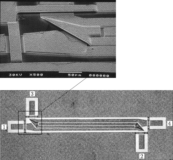


Figure 9-18. Photo of the Coplanar interdigital Coupler.
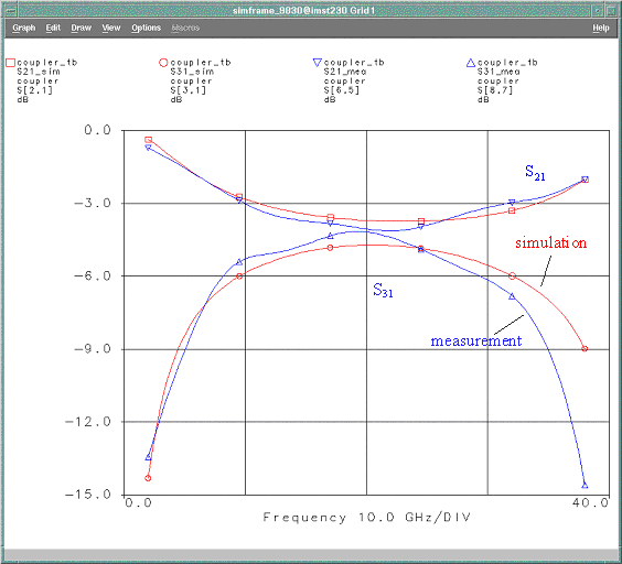


Figure 9-19. Insertion loss and coupling of the Coplanar interdigital Coupler.
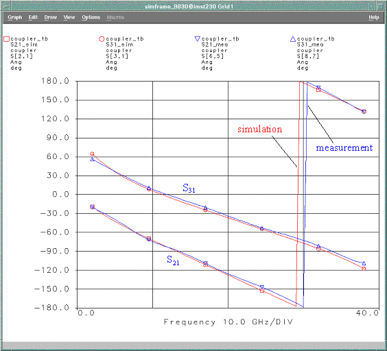


Figure 9-20. Phase of insertion loss and coupling of the Coplanar interdigital Coupler.


[close window] [10 References]