[close window] [2.9 Simulation Time]

2.10 Effect of Shielding


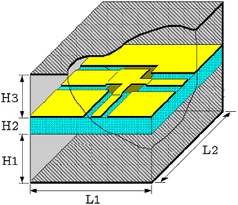
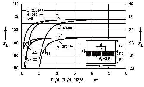
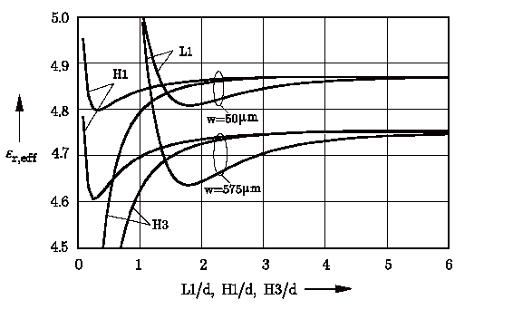
The accuracy of the applied method depends also on the size of shielding box. The width L1 and the depth L2 of the shielding box can be specified using the data item C_GRID (see chapter 4). The distance to the cover shield H3 as well as the distance to the bottom shield H1 have to be selected in C_SUB (see chapter 4). The influences of electric shielding walls (parameter L1, H1, H3) are investigated for two different CPW lines with the same total width d (d=W+2S) and different center line widths W (50 mm and 575 mm). The results are plotted in Figure 2-10. The width of the box L1 (distance to the lateral electrical walls) is the critical parameter specially in case of eeff calculations, whereas the distance to the upper and lower cover has a marginal effect. It is necessary to select L1 > 5d in order to keep the influence of the lateral shielding walls as small as possible. For H1 and H3, a value of 2d is mostly sufficient.
The effects of shielding on the calculated model parameters for 3-dimensional structures (discontinuities and lumped elements) are investigated in case of a coplanar step. In Figure 2-11, the relative error by the calculation of the step capacitance (upper diagram) and step inductance (lower diagram) are plotted against the shielding dimensions. The parameter L2 which indicates the distance to the magnetic walls must be 10d (d=max(W1+2S1, W2+2S2)) in order to neglect the effects of magnetic walls.

Since the effect of shielding depends on several
dimensional and material parameters, automated
box sizing is implemented. The user can select
negative values (–1 or –2) for the parameter L1
and L2 in related C_GRID data item as well as for
H1 and H3 in related C_SUB data item in order to
use the automated box sizing. In this case the shielding
sizes are automatically adapted to the structure
dimensions so that the influence of these walls on
field characteristics of the structure is negligible
(see descriptions in C_GRID and C_SUB in chapter 4).


Figure 2-10.Dependence of the line impedance ZL and effective permittivity eeff of coplanar waveguide on shielding sizes (d=w+2s)
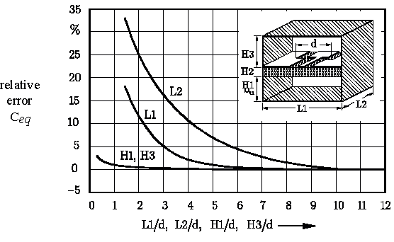
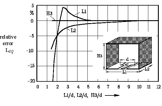


Figure 2-11.Dependence of the calculated model parameters of a coplanar step on shielding sizes (d=w2+2s2)


[close window] [2.11 Useful Hints]