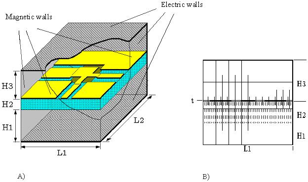
Figure 2-3.A) Shielded multi-layered substrate used for the field calculation.
B) Non-equidistant discretization as used in Coplan for ADS.
| [close window] | [2.4 Finite Difference Formulation] |
| [close window] | [2.2 Broadband Modeling] |
For the calculation of the electric and magnetic field distribution, the coplanar structure is surrounded by a shield of electric and magnetic walls (Figure 2-3A). Magnetic walls are assumed at ports, where the feed lines intersect the shielding. The distance between the magnetic walls and reference planes of the structure (length of feed lines at ports) effects the accuracy of the results and should therefore be chosen properly. The distance of electric walls from the structure should also be large enough in order to keep their effects as small as possible. An exception is the case where the effects of packaging should be taken into account. The dielectric constant of the area above and below the structure can differ from the value for air (er=1). In this way, multilayer substrate configurations can be calculated.
The volume inside the shielding box is now divided into elementary cells using a 3 dimensional non-equidistant grid (Figure 2-3B). The discretization is done automatically in such a way that the area near the metalization surface is discretized much finer than the space above and below the substrate surface. The reason is the fact that the field is more concentrated near by the metalization surface. For the implementation of this method in a CAD-tool and in order to speed up the calculation , an efficient and automatic discretization is implemented.

Figure 2-3.A) Shielded multi-layered substrate used for the field calculation.
B) Non-equidistant discretization as used in Coplan for ADS.
| [close window] | [2.4 Finite Difference Formulation] |