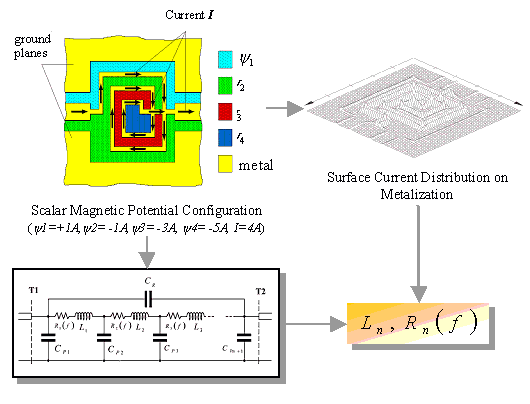
Figure 2-6. Magnetic potential configuration for the calculation of the equivalent inductances of a spiral inductor
| [close window] | [2.5 Capacitive Model Parameters] |
To determine the equivalent inductances, NAGHED introduced in [2.4] the following procedure. First of all, a given geometry must be inverted, that means, the slots become metal and vice versa (Figure 2-6). Because of the fact that the slots in coplanar structures act as the magnetic wall, constant magnetic scalar potentials are assumed in the area of slots between the metalization. After that, the magnetic scalar potential can be calculated similar to the electrical potential.

Once the magnetic field in the coplanar slots is known, the integral over the slot surface leads to the magnetic flux and the surface current distribution, which is used for the calculation of the total flux of the structure. Since the magnetic potential difference in slots is known to be y, the equivalent inductance (Leq) is then calculated from the difference between the total flux and the flux per unit length multiplied by the geometrical length of the virtual coplanar lines at ports:
where l is defined as the virtual distance between the back-transformed reference planes of the discontinuity and the magnetic walls.,